EFR32 ZDDC 设备开发
本文将介绍如何在 EFR32 上使用 ZDDC 协议和 ACOINFO ZigBee 通用设备应用规范开发一个能接入到 EdgerOS 的 ZigBee 智能设备。
硬件准备
EFR32 开发板
EFR32 是 Silicon lab 推出的同时集成 RF 射频收发器和 ARM Cortex M4 内核 MCU 的无线射频 SOC 解决方案。其主频为 40MHz,片上最高输出功率可达 20dBm(Sub1GHz:20dBm,2.4GHZ:19.5dBm)。内置 32KB RAM 和 256KB Flash。拥有丰富的外设资源,其射频部分可同时覆盖 2.4GHz 和 Sub1GHz 频段。
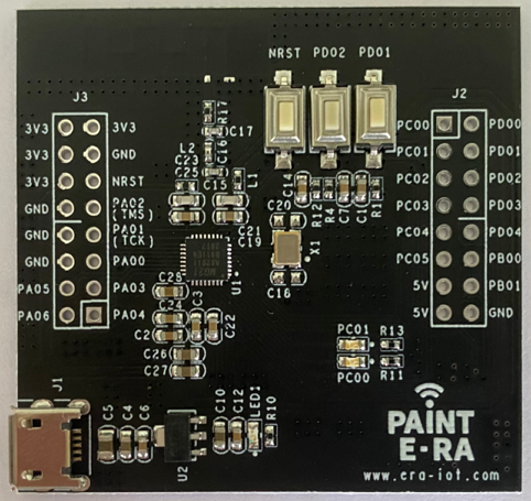
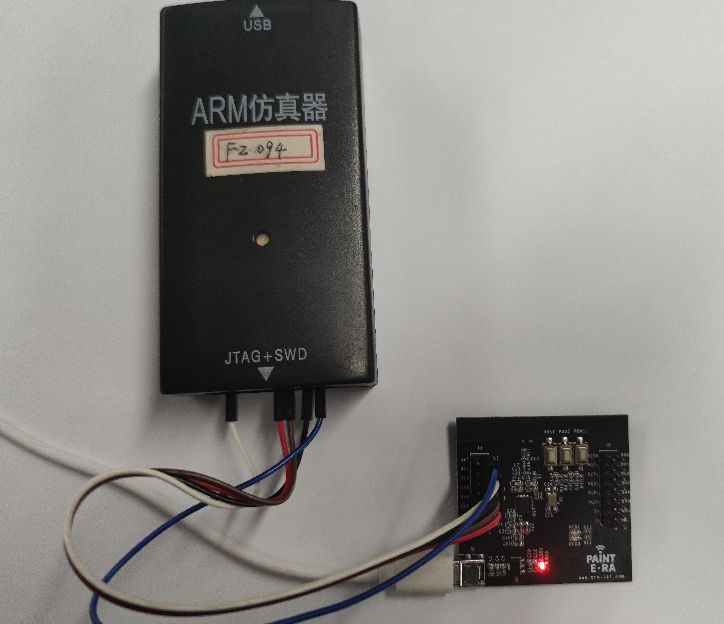
本实验使用的是一块画时科技的 EFR32 开发板,芯片型号为 EFR32MG21A020F768IM32 实物图如下所示:
软件准备
开发 EFR32 需要使用 Simplicity Studio IDE。
下载 IDE 软件包并安装
网盘链接:https://pan.baidu.com/s/1ZbmzPaex95f0cD4CHz4ztg 提取码:lvle
解压 SimplicityStudio-EmberZnet 6.7.8.0-WIN10.7z 文件到 D:\ ,进入 D:\v4 目录双击 studio.exe 打开 IDE ,
出现创建 workspace 失败,不需理会:
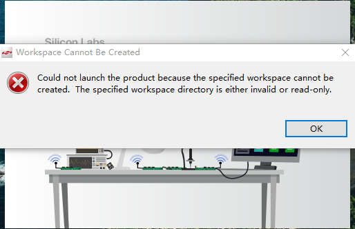
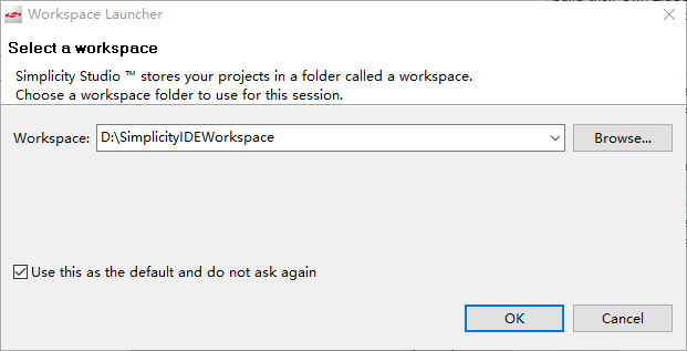
点击两次 OK 后会进入选择 workspace 界面,选择或创建 workspace 如下所示:
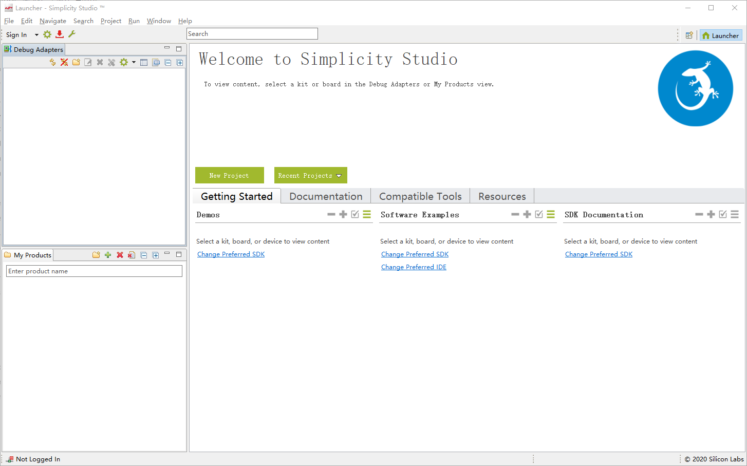
检查更新后主界面如下所示:
新建工程
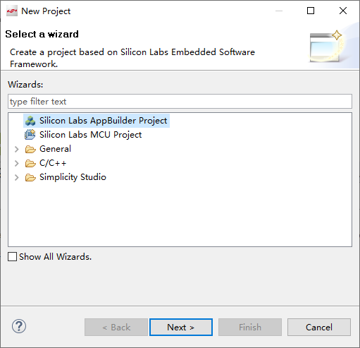
点击 File > New > Project ,选择 Silicon Labs AppBuilder Project ,点击 Next 如下所示:
选择 Silicon Labs Zigbee 后点击 Next 如下所示:

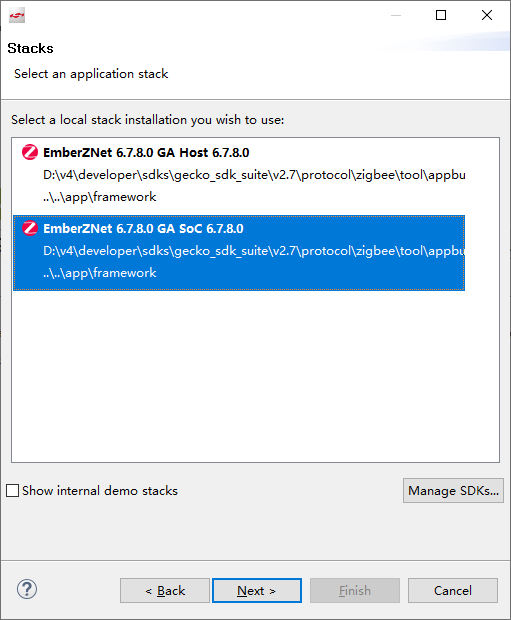
选择 EmberZNet 6.7.8.0 GA SoC 6.7.8.0 后点击 Next 如下所示:
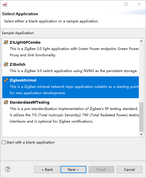
选择 ZigbeeMinimal 后点击 Next 如下所示:
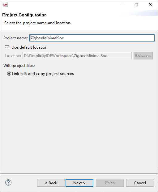
设置 Project name 后点击 Next 如下所示:
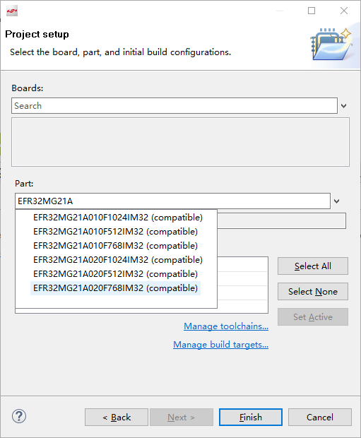
选择 Part 为 EFR32MG21A020F768IM32 后点击 Finish 如下所示:
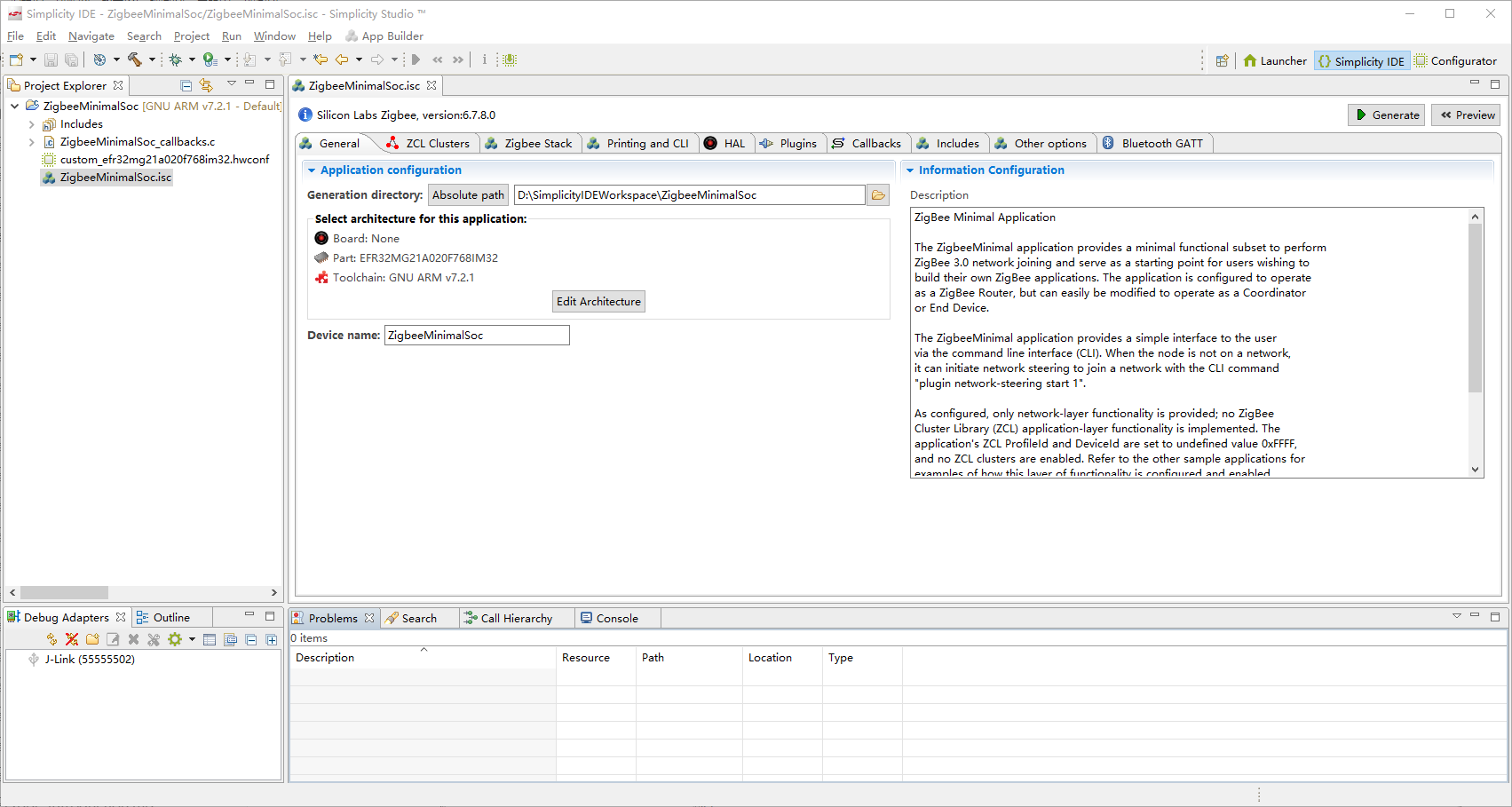
至此工程创建完成:
配置工程
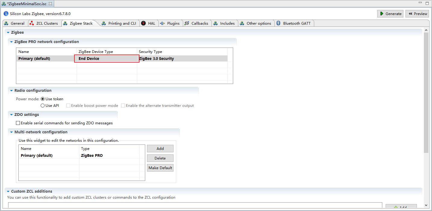
选择 ZigbeeMinimalSoc.isc 文件中的 Zigbee Stack 选项,选择 Zigbee Device Type 为 End Device 如下所示:
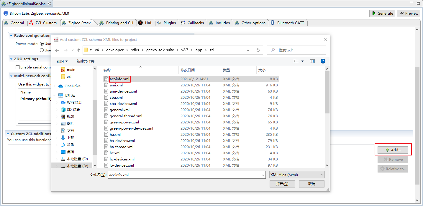
复制附录中的 acoinfo 自定义 Cluster 扩展规范文件 acoinfo.xml ,拷贝到 D:\v4\developer\sdks\gecko_sdk_suite\v2.7\app\zcl 目录下,Zigbee Stack 选项中点击 Add... ,添加 acoinfo.xml 到工程中,如下所示:
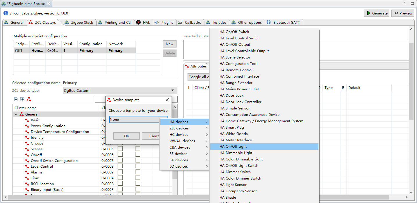
选择 ZCL Clusters 选项,按照下图所示选择 HA On/Off Light :
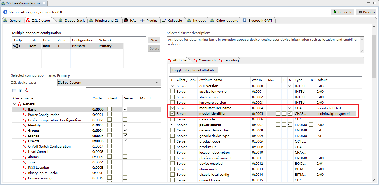
选择 ZCL Clusters 选项,点击下方 General 中的 Basic 在右侧添加 manufacturer name 为 acoinfo.light.led ,model id 为 acoinfo.zigbee.generic 如下所示:
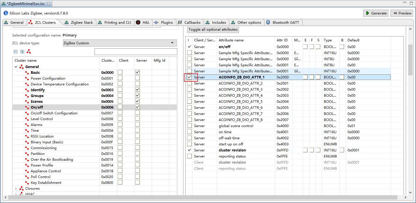
选择 General 中的 On/Off ,勾选 DIO 通道 1,如下所示:
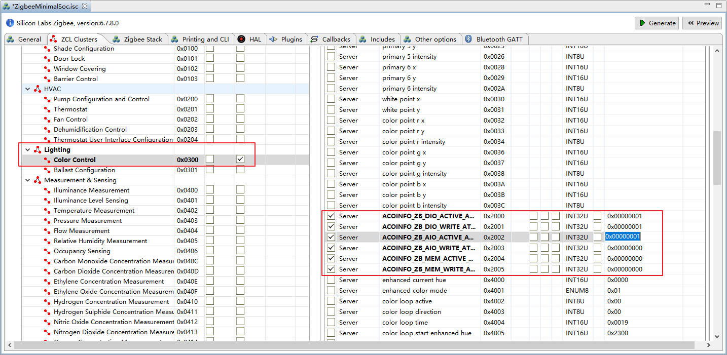
选择 Lighting 中的 Color Control ,在右侧选择 acoinfo 自定义的六个 attribute ,修改 DIO 通道可用和可写以及 AIO 通道的可用的默认值为 0x00000001,如下所示:
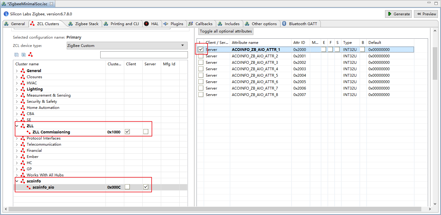
勾选 ZLL 中的 ZLL Commissioning ,以及 acoinfo 中的 acoinfo_aio 中的 AIO 通道 1,如下所示:
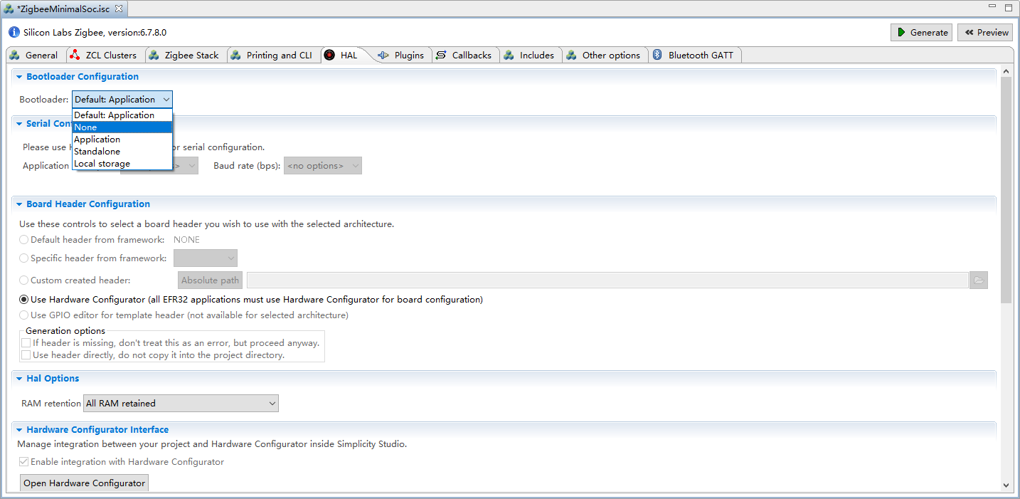
选择 HAL 选项中的 Bootloader,设置为 None,如下所示:
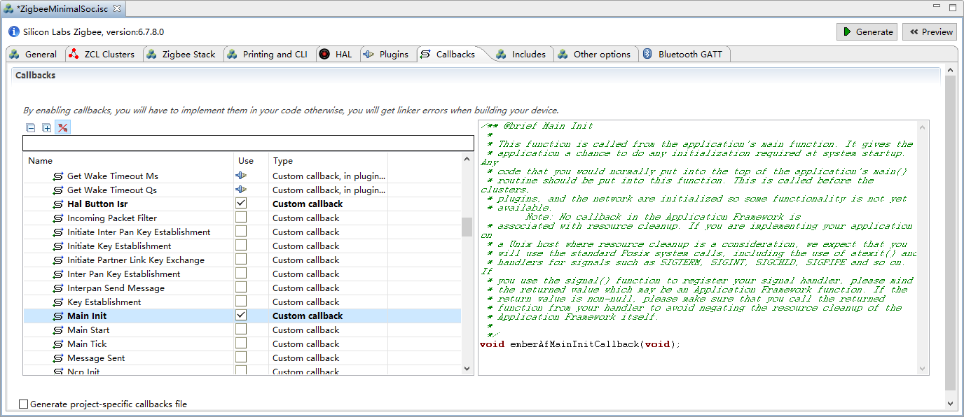
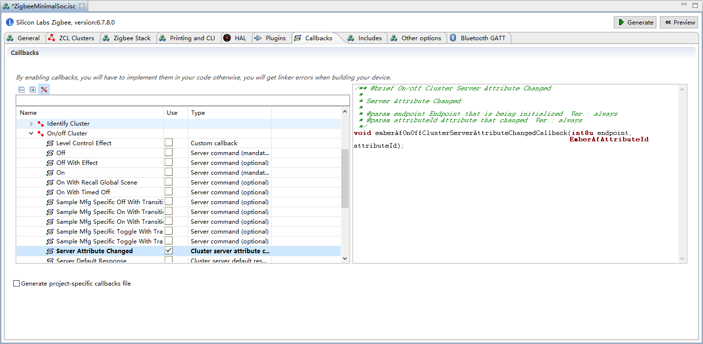
选择 Callbacks 选项,选中 Main Init 选项、Hal Button Isr 选项以及 Server Attribute Changed 选项,如下所示:
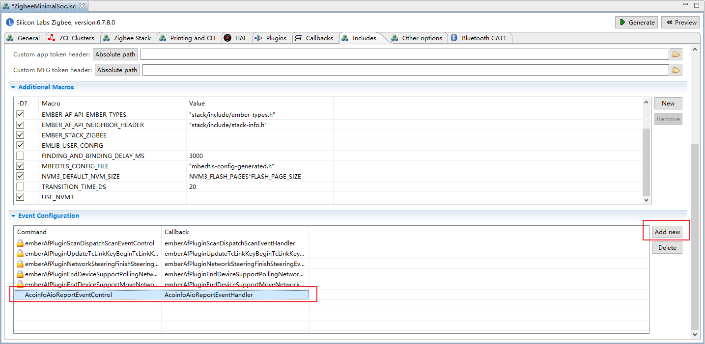
选择 Includes 选项,点击 Add new 添加一个自定义事件,用于定期上报模拟量通道 1,Command 为 AcoinfoAioReportEventControl ,Callback 为 AcoinfoAioReportEventHandler ,如下所示:
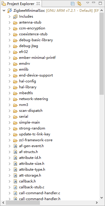
保存后点击右上角 Generate 后会生成代码,如下所示:
双击 ZigbeeMinimalSoc_callbacks.c 文件,在文件末尾加入上面选中的 emberAfMainInitCallback,并延时调用周期上报 AIO 事件,如下所示:
void emberAfMainInitCallback(void)
{
    emberAfCorePrintln("---------------test---------------");
    emberEventControlSetDelayMS(AcoinfoAioReportEventControl, 10000);
}
在上述文件中加入周期上报 AIO 处理函数 AcoinfoAioReportEventHandler ,如下所示:
EmberEventControl AcoinfoAioReportEventControl;
void AcoinfoAioReportEventHandler(void)
{
    // 在下次使用之前禁用该事件
    emberEventControlSetInactive(AcoinfoAioReportEventControl);

    float data = 3.14;
    uint8_t * p_data = (uint8_t *)&data;
    uint8_t buf[7] = {0};
    buf[0] = ZCL_ACOINFO_ZB_AIO_ATTR_1_ATTRIBUTE_ID && 0xFF;
    buf[1] = ZCL_ACOINFO_ZB_AIO_ATTR_1_ATTRIBUTE_ID >> 8;
    buf[2] = ZCL_FLOAT_SINGLE_ATTRIBUTE_TYPE;
    for(int i=0;i<4;i++){
        buf[3+i] = *p_data++;
    }
    emberAfFillCommandGlobalServerToClientReportAttributes(ZCL_ACOINFO_ZB_AIO_CLUSTER_ID,
                                                           (uint8_t *)buf, 7);
    emberAfSetCommandEndpoints(1, 1);
    emberAfSendCommandUnicast(EMBER_OUTGOING_DIRECT, 0x0000);

    // 延迟 5 秒后重新触发事件
    emberEventControlSetDelayMS(AcoinfoAioReportEventControl, 5000);
}
在上述文件中加入监听 DIO 值变化回调函数,并加入开关 LED 灯的功能, 如下所示:
void emberAfOnOffClusterServerAttributeChangedCallback(int8u endpoint,
                                                       EmberAfAttributeId attributeId)
{
    EmberAfStatus status;
    uint8_t data[1];

      status = emAfReadAttribute(endpoint,
                                 ZCL_ON_OFF_CLUSTER_ID,
                                 attributeId,
                                 0x40,
                                 0x0000,
                                 data,
                                 1,
                                 NULL);
      if (status == EMBER_ZCL_STATUS_SUCCESS) {
          if(attributeId == ZCL_ACOINFO_ZB_DIO_ATTR_1_ATTRIBUTE_ID){
              if(data[0] == 0x01){
                  halSetLed(1);    // 开启 LED 灯
                  emberAfCorePrintln("led on");
              } else if(data[0] == 0x00) {
                  halClearLed(1); // 关闭 LED 灯
                  emberAfCorePrintln("led off");
              } else {
                  emberAfCorePrintln("data error");
              }
          }
      } else {
          emberAfCorePrintln("read attribute failed... status = %x", status);
      }
}
在上述文件中加入 BUTTON 监听回调函数,检测按下后开始配置入网,如下所示:
void emberAfHalButtonIsrCallback(uint8_t button, uint8_t state)
{
  if (state == BUTTON_RELEASED) {
      emberAfPluginNetworkSteeringStart();
  }
}
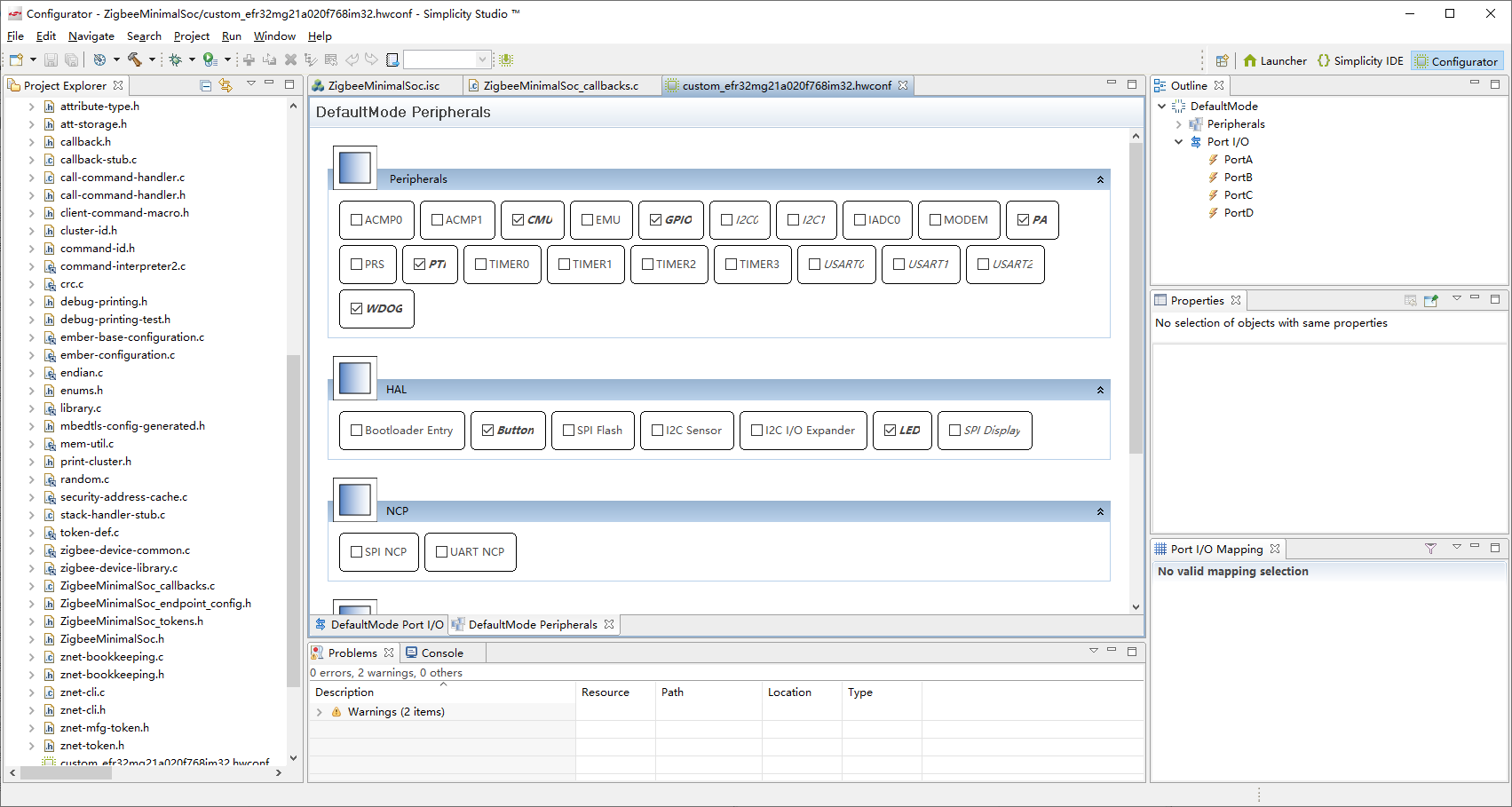
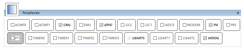
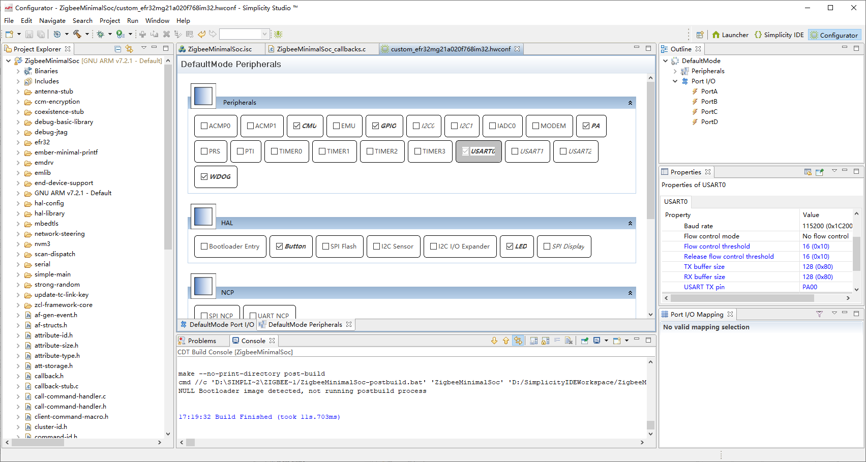
双击左侧 custom_efr32mg21a020f768im32.hwconf 文件后点击下方 DefaultMode Peripherals 选项来配置管脚:
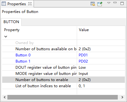
根据开发板 Button 设置如下所示:
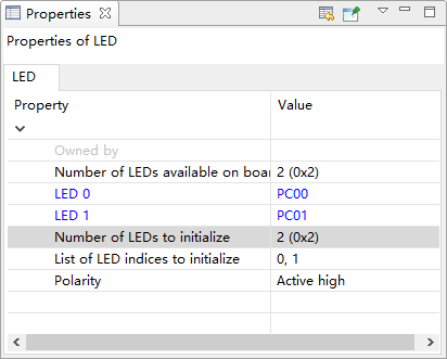
根据开发板 LED 设置如下所示:
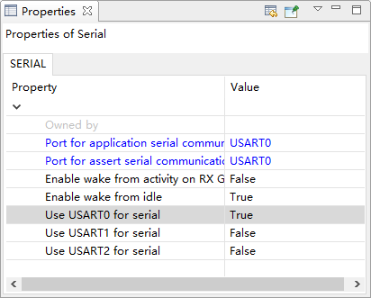
设置日志输出配置如下所示:
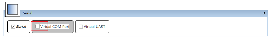
取消勾选 Virtual COM Port :
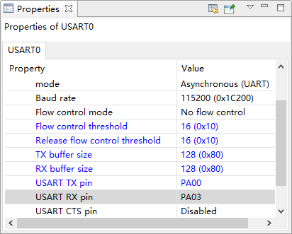
设置 USART0 如下所示:
取消勾选 PTI:
保存后会生成相关硬件配置代码,点击编译生成二进制文件:
烧写镜像
使用 JLink 把开发板连接到 PC,如下所示:
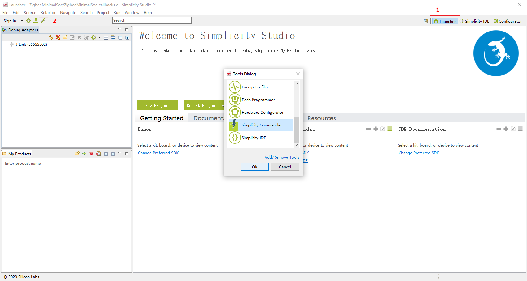
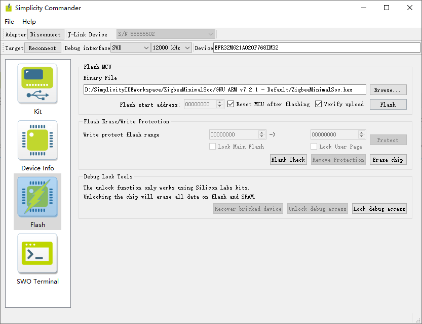
点击右上角 Launcher 进入主页,再点击左侧工具图标,在弹出框中选择 Simplicity Commander 后点击 OK:
选择左侧第三个选项 Flash,然后依次点击上方 Adapter 和 Target 右边的 Connect 按键,点击 Browse 选择对应路径下的 Z3SwitchSoc.hex 文件,点击 Erase chip 擦除,点击 Flash 进行烧写,如下所示:
入网验证
验证前,请参考《 ZDDC 协议介绍》章节中的 ZigBee 设备入网流程,完成以下步骤:
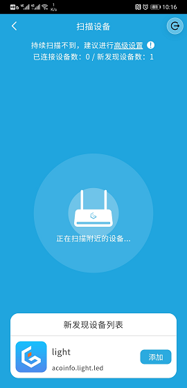
进入扫描设备界面,如下图所示:

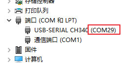
将 EFR32 开发板接入 PC,打开设备管理器,查看 PC 为 EFR32 开发板分配的 COM 号,如下图所示:
使用 PuTTY 作为串口调试工具,打开 PuTTY 进入 PuTTY Configuration 界面,选择 Session 类, Connection type 选择:Serial ,Serial line 为 EFR32 开发板接入 PC 后分配的 COM 号(如
COM23),Speed 设置为115200,最后点击 Open 按键进入 PuTTY 终端: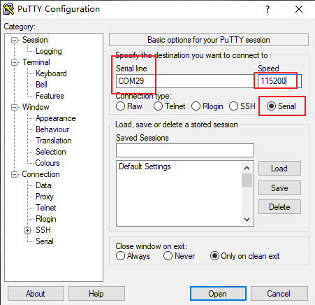
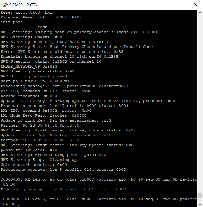
开发板上电,按下 PD01 执行关联入网操作,串口打印结果如下图所示:
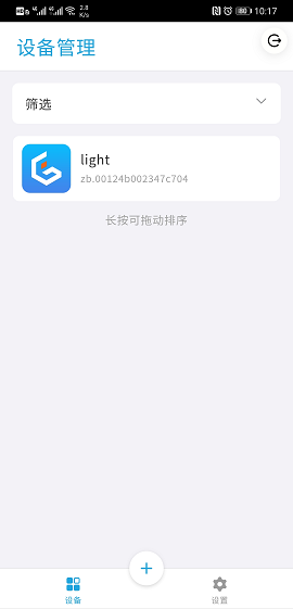
此时,EdgerOS 会发现新的设备,点击添加按钮完成新设备的添加:
附录
acoinfo.xml 文件
<configurator>
  <domain name="acoinfo" />
  <cluster>
    <name>acoinfo_aio</name>
    <domain>acoinfo</domain>
    <description>Acoinfo custom cluster</description>
    <code>0x000C</code>
    <define>ACOINFO_ZB_AIO_CLUSTER</define>
    <client init="false" tick="false">true</client>
    <server init="false" tick="false">true</server>
    <attribute side="server" code="0x2000" define="ACOINFO_ZB_AIO_ATTR_1"
      type="INT32U"  min="0x00000000"   max="0xFFFFFFFF"   writable="true"
      default="0x00000000" optional="true">ACOINFO_ZB_AIO_ATTR_1</attribute>
    <attribute side="server" code="0x2001" define="ACOINFO_ZB_AIO_ATTR_2"
      type="INT32U"  min="0x00000000"   max="0xFFFFFFFF"   writable="true"
      default="0x00000000" optional="true">ACOINFO_ZB_AIO_ATTR_2</attribute>
    <attribute side="server" code="0x2002" define="ACOINFO_ZB_AIO_ATTR_3"
      type="INT32U"  min="0x00000000"   max="0xFFFFFFFF"   writable="true"
      default="0x00000000" optional="true">ACOINFO_ZB_AIO_ATTR_3</attribute>
    <attribute side="server" code="0x2003" define="ACOINFO_ZB_AIO_ATTR_4"
      type="INT32U"  min="0x00000000"   max="0xFFFFFFFF"   writable="true"
      default="0x00000000" optional="true">ACOINFO_ZB_AIO_ATTR_4</attribute>
    <attribute side="server" code="0x2004" define="ACOINFO_ZB_AIO_ATTR_5"
      type="INT32U"  min="0x00000000"   max="0xFFFFFFFF"   writable="true"
      default="0x00000000" optional="true">ACOINFO_ZB_AIO_ATTR_5</attribute>
    <attribute side="server" code="0x2005" define="ACOINFO_ZB_AIO_ATTR_6"
      type="INT32U"  min="0x00000000"   max="0xFFFFFFFF"   writable="true"
      default="0x00000000" optional="true">ACOINFO_ZB_AIO_ATTR_6</attribute>
    <attribute side="server" code="0x2006" define="ACOINFO_ZB_AIO_ATTR_7"
      type="INT32U"  min="0x00000000"   max="0xFFFFFFFF"   writable="true"
      default="0x00000000" optional="true">ACOINFO_ZB_AIO_ATTR_7</attribute>
    <attribute side="server" code="0x2007" define="ACOINFO_ZB_AIO_ATTR_8"
      type="INT32U"  min="0x00000000"   max="0xFFFFFFFF"   writable="true"
      default="0x00000000" optional="true">ACOINFO_ZB_AIO_ATTR_8</attribute>
  </cluster>

  <clusterExtension code="0x0006">
    <attribute side="server" code="0x2000"
      define="ACOINFO_ZB_DIO_ATTR_1"
      type="BOOLEAN" min="0x00" max="0x01" writable="true"
      default="0x00" optional="true">ACOINFO_ZB_DIO_ATTR_1</attribute>
    <attribute side="server" code="0x2001"
      define="ACOINFO_ZB_DIO_ATTR_2"
      type="BOOLEAN" min="0x00" max="0x01" writable="true"
      default="0x00" optional="true">ACOINFO_ZB_DIO_ATTR_2</attribute>
    <attribute side="server" code="0x2002"
      define="ACOINFO_ZB_DIO_ATTR_3"
      type="BOOLEAN" min="0x00" max="0x01" writable="true"
      default="0x00" optional="true">ACOINFO_ZB_DIO_ATTR_3</attribute>
    <attribute side="server" code="0x2003"
      define="ACOINFO_ZB_DIO_ATTR_4"
      type="BOOLEAN" min="0x00" max="0x01" writable="true"
      default="0x00" optional="true">ACOINFO_ZB_DIO_ATTR_4</attribute>
    <attribute side="server" code="0x2004"
      define="ACOINFO_ZB_DIO_ATTR_5"
      type="BOOLEAN" min="0x00" max="0x01" writable="true"
      default="0x00" optional="true">ACOINFO_ZB_DIO_ATTR_5</attribute>
    <attribute side="server" code="0x2005"
      define="ACOINFO_ZB_DIO_ATTR_6"
      type="BOOLEAN" min="0x00" max="0x01" writable="true"
      default="0x00" optional="true">ACOINFO_ZB_DIO_ATTR_6</attribute>
    <attribute side="server" code="0x2006"
      define="ACOINFO_ZB_DIO_ATTR_7"
      type="BOOLEAN" min="0x00" max="0x01" writable="true"
      default="0x00" optional="true">ACOINFO_ZB_DIO_ATTR_7</attribute>
    <attribute side="server" code="0x2007"
      define="ACOINFO_ZB_DIO_ATTR_8"
      type="BOOLEAN" min="0x00" max="0x01" writable="true"
      default="0x00" optional="true">ACOINFO_ZB_DIO_ATTR_8</attribute>
  </clusterExtension>

  <clusterExtension code="0x0300">
    <attribute side="server" code="0x2000" define="ACOINFO_ZB_DIO_ACTIVE_T_ATTR"
      type="INT32U"  min="0x00000000"   max="0xFFFFFFFF"   writable="true"
      default="0x00000000" optional="true">ACOINFO_ZB_DIO_ACTIVE_ATTR</attribute>
    <attribute side="server" code="0x2001" define="ACOINFO_ZB_DIO_WRITE_T_ATTR"
      type="INT32U"  min="0x00000000"   max="0xFFFFFFFF"   writable="true"
      default="0x00000000" optional="true">ACOINFO_ZB_DIO_WRITE_ATTR</attribute>
    <attribute side="server" code="0x2002" define="ACOINFO_ZB_AIO_ACTIVE_T_ATTR"
      type="INT32U"  min="0x00000000"   max="0xFFFFFFFF"   writable="true"
      default="0x00000000" optional="true">ACOINFO_ZB_AIO_ACTIVE_ATTR</attribute>
    <attribute side="server" code="0x2003" define="ACOINFO_ZB_AIO_WRITE_T_ATTR"
      type="INT32U"  min="0x00000000"   max="0xFFFFFFFF"   writable="true"
      default="0x00000000" optional="true">ACOINFO_ZB_AIO_WRITE_ATTR</attribute>
    <attribute side="server" code="0x2004" define="ACOINFO_ZB_MEM_ACTIVE_T_ATTR"
      type="INT32U"  min="0x00000000"   max="0xFFFFFFFF"   writable="true"
      default="0x00000000" optional="true">ACOINFO_ZB_MEM_ACTIVE_ATTR</attribute>
    <attribute side="server" code="0x2005" define="ACOINFO_ZB_MEM_WRITE_T_ATTR"
      type="INT32U"  min="0x00000000"   max="0xFFFFFFFF"   writable="true"
      default="0x00000000" optional="true">ACOINFO_ZB_MEM_WRITE_ATTR</attribute>
  </clusterExtension>

  <clusterExtension code="0x0500">
    <attribute side="server" code="0x2000"
      define="ACOINFO_ZB_MEM_ATTR_1"
      type="INT32U" min="0x00000000" max="0xFFFFFFFF" writable="true"
      default="0x00000000" optional="true">ACOINFO_ZB_MEM_ATTR_1</attribute>
    <attribute side="server" code="0x2001"
      define="ACOINFO_ZB_MEM_ATTR_2"
      type="INT32U" min="0x00000000" max="0xFFFFFFFF" writable="true"
      default="0x00000000" optional="true">ACOINFO_ZB_MEM_ATTR_2</attribute>
    <attribute side="server" code="0x2002"
      define="ACOINFO_ZB_MEM_ATTR_3"
      type="INT32U" min="0x00000000" max="0xFFFFFFFF" writable="true"
      default="0x00000000" optional="true">ACOINFO_ZB_MEM_ATTR_3</attribute>
    <attribute side="server" code="0x2003"
      define="ACOINFO_ZB_MEM_ATTR_4"
      type="INT32U" min="0x00000000" max="0xFFFFFFFF" writable="true"
      default="0x00000000" optional="true">ACOINFO_ZB_MEM_ATTR_4</attribute>
    <attribute side="server" code="0x2004"
      define="ACOINFO_ZB_MEM_ATTR_5"
      type="INT32U" min="0x00000000" max="0xFFFFFFFF" writable="true"
      default="0x00000000" optional="true">ACOINFO_ZB_MEM_ATTR_5</attribute>
    <attribute side="server" code="0x2005"
      define="ACOINFO_ZB_MEM_ATTR_6"
      type="INT32U" min="0x00000000" max="0xFFFFFFFF" writable="true"
      default="0x00000000" optional="true">ACOINFO_ZB_MEM_ATTR_6</attribute>
    <attribute side="server" code="0x2006"
      define="ACOINFO_ZB_MEM_ATTR_7"
      type="INT32U" min="0x00000000" max="0xFFFFFFFF" writable="true"
      default="0x00000000" optional="true">ACOINFO_ZB_MEM_ATTR_7</attribute>
    <attribute side="server" code="0x2007"
      define="ACOINFO_ZB_MEM_ATTR_8"
      type="INT32U" min="0x00000000" max="0xFFFFFFFF" writable="true"
      default="0x00000000" optional="true">ACOINFO_ZB_MEM_ATTR_8</attribute>
  </clusterExtension>
</configurator>


 陕公网安备61019002002605号